C42 Design Breakdown
C42 Polar Alignment: Start Shooting Sooner, or Refine Further
How C42 combines AR and plate-solving polar alignment, with on-screen guidance to help you start quickly or refine alignment for deep-sky imaging.
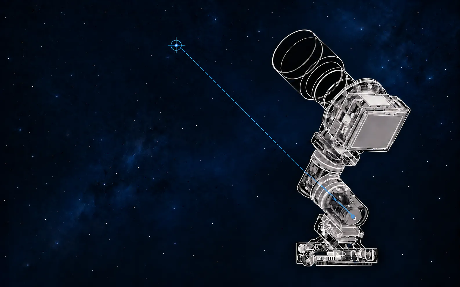
C42 is designed for astrophotographers who care about image quality, across the related but distinct worlds of nightscape and deep-sky photography. In designing the polar alignment workflow, we first asked: why not use an alt-azimuth mount? We want photographers to work comfortably near the zenith, where sustained tracking is more demanding for an alt-azimuth mount. That is why we chose an equatorial mount. The choice also brings a task to complete before shooting: polar alignment.
Speed and precision take different priorities in these two settings. Nightscape photographers usually work at shorter focal lengths, bringing the sky, celestial objects, landscapes, and people into one photograph during a fleeting moment. They need to start quickly, with the accuracy the photograph requires. Deep-sky photographers point longer focal lengths at a target, aiming for longer individual exposures and more material over the night. Their priority is to get the polar axis accurately aligned, then get shooting promptly.
C42 brings AR and plate-solving polar alignment into one workflow to meet both needs: AR establishes the direction quickly; plate solving reduces the remaining error further. You can start shooting immediately after AR alignment or continue with plate solving to refine the alignment for deep-sky imaging. Each choice between speed and precision reflects a real way of working under the stars.
Tap the telescope-shaped icon at the bottom right of the main screen, then select Polar align from the control menu. Follow the prompts to set the initial heading, tilt angle, and base position. You will then reach Star map alignment, the AR polar alignment stage.
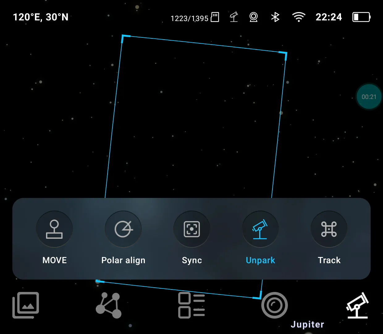
Open the bottom-right control menu to find Polar align.
AR polar alignment: Find the direction, then refine with real stars
Polar alignment makes the mount’s right ascension axis parallel to Earth’s rotation axis so it can track the apparent motion of the sky more accurately. In the Northern Hemisphere, the target direction is the NCP, or North Celestial Pole. Polaris happens to lie close to this point, but not exactly on it. Earth’s axis also slowly changes direction through precession. Simply centering Polaris in the image does not mean the mount is correctly polar-aligned.
AR polar alignment first uses a star map to help you find the right direction. The red frame marks the target position centered on the NCP; the blue frame shows the field of view at the current pointing direction. Turn the azimuth and altitude adjustment knobs on the base until the frames overlap, bringing the equipment close to the target direction.
The next step presents a Live View window, much like the viewfinder of a mirrorless camera when shooting the night sky. Two reference markers are overlaid on the image: α UMi is Polaris, and λ UMi is Lambda Ursae Minoris. Make small azimuth and altitude adjustments until each captured star matches its corresponding marker, refining the polar alignment.
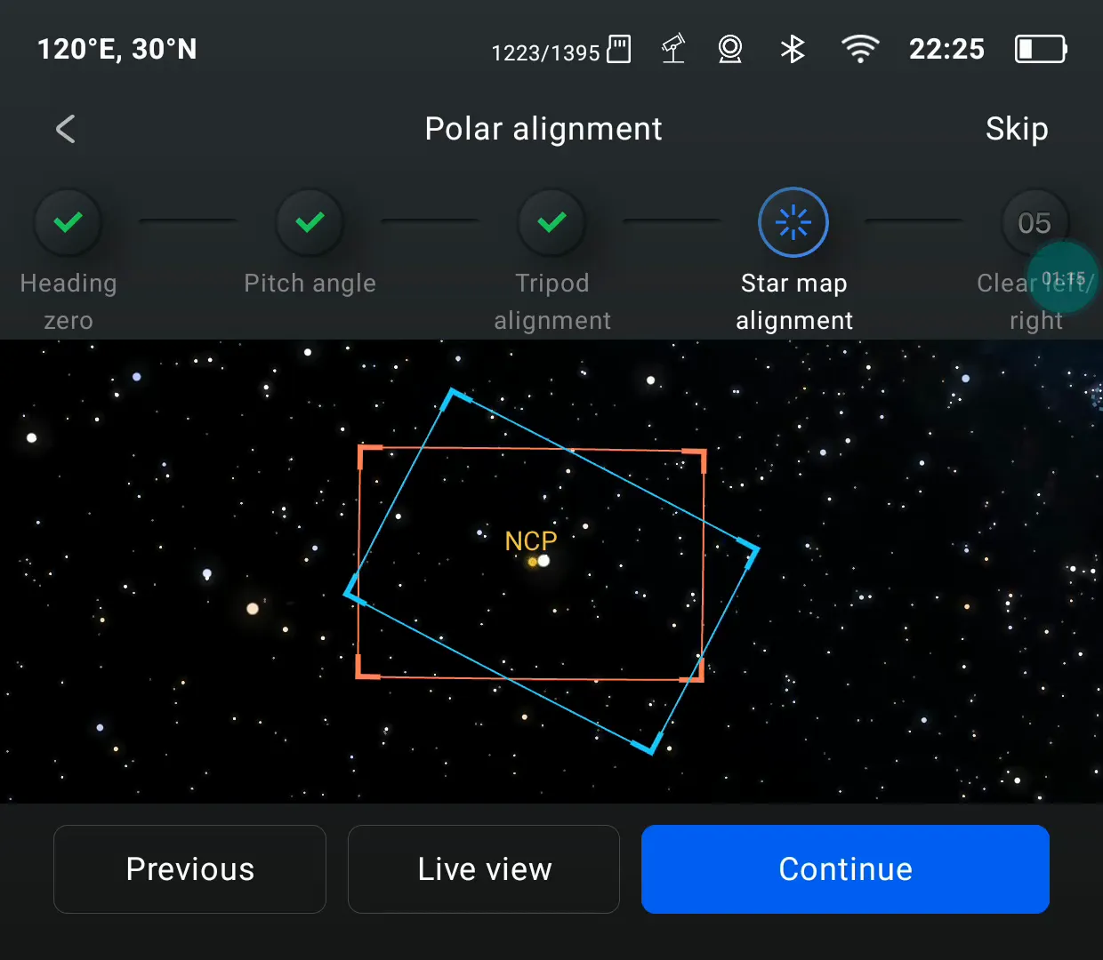
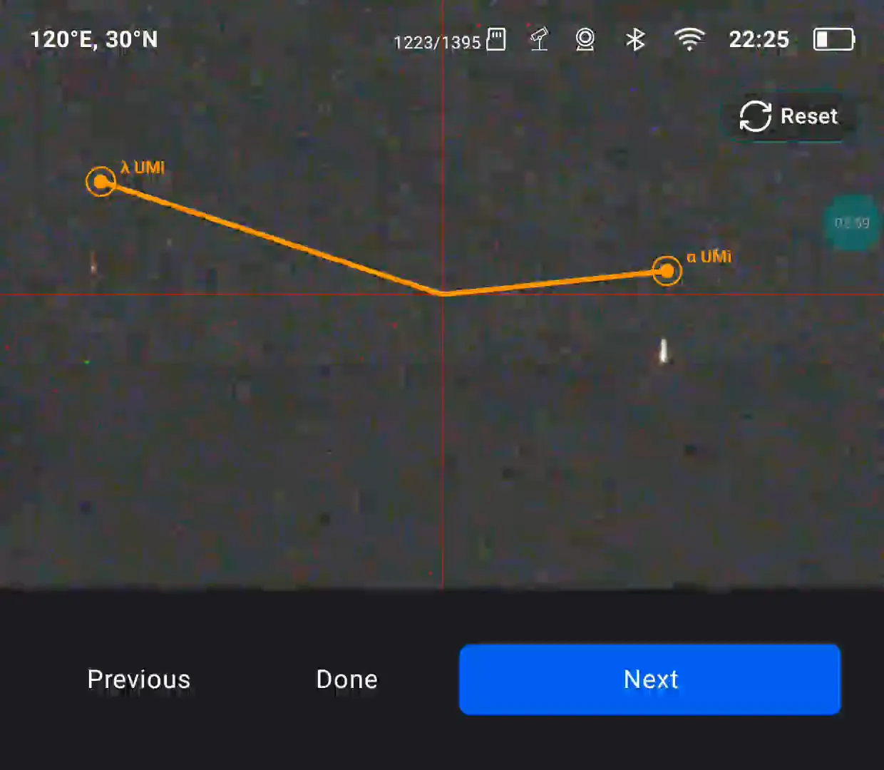
First overlap the frames on the star map, then refine the alignment using the stars actually captured by the camera.
A traditional optical polar scope requires you to look through an eyepiece, check the position of a reference star against the reticle markings, and adjust the polar axis accordingly. C42 displays the real star field and reference markers on the screen, letting you adjust while watching the image without checking star positions through a polar scope’s eyepiece.
For wide-angle imaging where time is limited and alignment requirements are less demanding, you can tap Done after completing AR polar alignment. If you want greater precision, tap Next to continue with plate-solving polar alignment.
Plate-solving polar alignment: Measure the error, then follow the adjustment prompts
The next screen asks whether the camera has an unobstructed view of the sky to the west or east. Select West clear or East clear, and the mount will automatically slew to that side. Once you have checked the view, tap Start calibration. The system captures three star-field images at different pointing directions, identifies the stars in them, and uses their positions to calculate the polar alignment error.
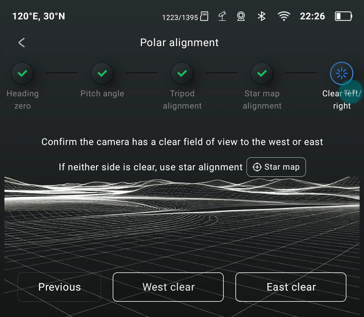
If both the eastern and western views are obstructed, tap Star map, choose a recommended position on the map, let the equipment slew there, and then start plate solving.
Once the error has been measured, the screen tells you which knob to turn, in which direction, and by how many turns. In the screenshot below, the upper illustration shows the azimuth adjustment, which changes the direction left or right. The lower illustration shows the altitude adjustment, which changes the direction up or down. Orange circles identify the knobs, while the arrows and turn counts show how to adjust them. 0.1 turns means turning that knob one tenth of a full revolution in the indicated direction.
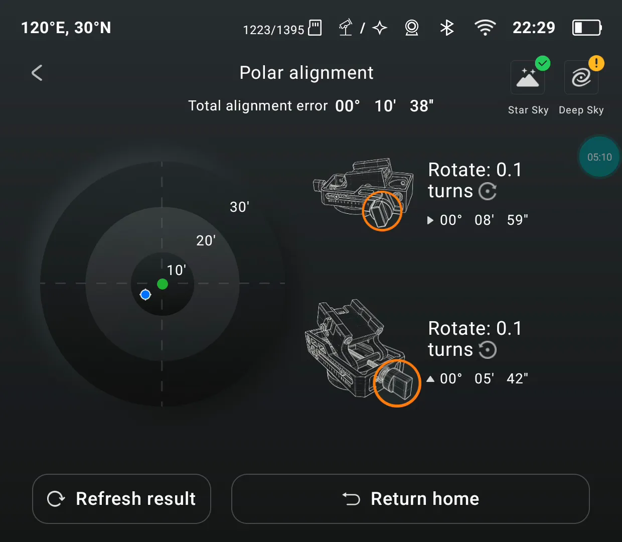
For this measurement, the screen calls for a 0.1-turn adjustment of each knob. Always follow the latest measurement.
The sequence of measuring error, turning a knob, and refreshing the result follows a principle familiar from many astronomy controllers. We wanted the physical adjustment to feel better too. Our mechanical design controls backlash while giving azimuth and altitude their own smooth, single-knob adjustment. Watch the prompts and turn the corresponding knob to make a precise correction.
After turning the knobs, tap Refresh result to measure again and display the remaining error. If more adjustment is needed, follow the new direction and turn-count prompts, then refresh again. Each measurement checks the effect of your last adjustment, helping you reduce the error step by step.
In this demonstration, the first plate-solving measurement after AR alignment showed a total error of 10′38″—10 arcminutes and 38 arcseconds. The Star Sky indicator already had a green check. After further adjustments and refreshed measurements, the total error fell to 1′01″—1 arcminute and 1 arcsecond, and Deep Sky also showed a green check.
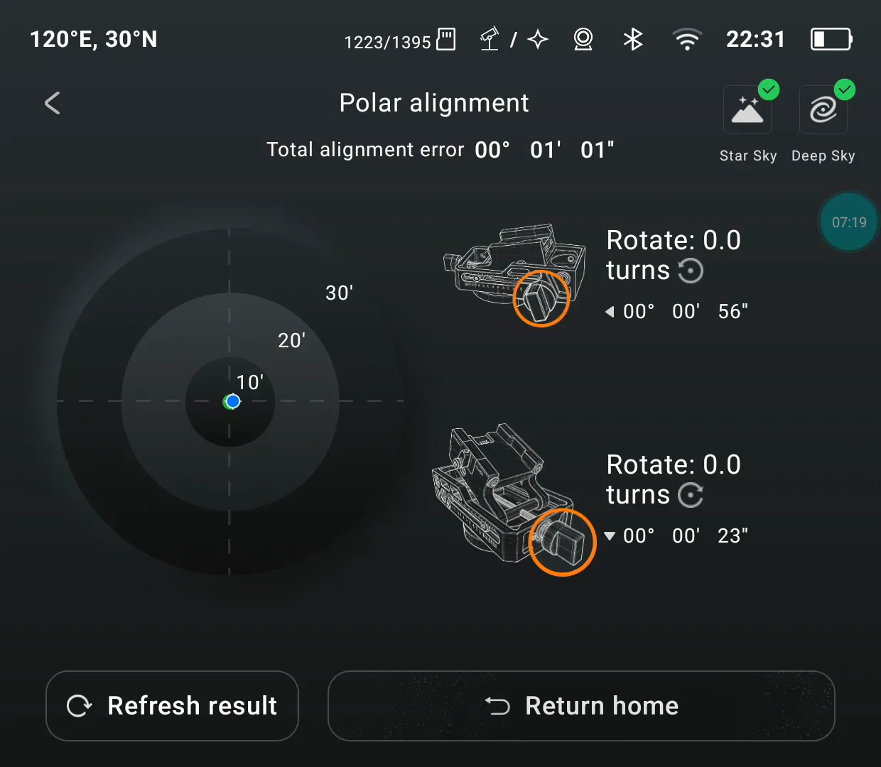
These are readings from this demonstration, not a guarantee of the same accuracy every time. The alignment accuracy your imaging requires also depends on focal length, individual exposure time, and guiding conditions.
The two methods follow one another in the workflow, but you do not have to complete both every time. For a quick wide-angle session, you can finish after AR polar alignment. For greater precision, continue with plate solving and refine the alignment using the measured results. C42 puts the direction, required adjustments, and remaining error on the screen to help you decide when you are ready to start shooting.
What Comes Next: No Further Manual Refinement After Plate Solving
We have another improvement planned: once plate solving is complete, closed-loop control across three axes will provide compensation without further fine manual adjustment. Pulsar’s right ascension and declination axes work with HALO’s composition rotation axis to make this possible. We look forward to bringing this capability to users through an OTA update.
